AFM principles
An atomic force microscope converts tip–sample interaction into a calibrated height or force signal. The image is not a direct photograph: it is the output of a sensor, feedback controller, scanner and reconstruction convention.
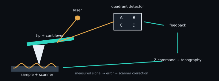
Tip, cantilever and interaction
A sharp tip sits at the end of a compliant cantilever. When the interaction force \(F\) is small enough for a linear cantilever model,
where \(k\) is spring constant in N m\(^{-1}\) and \(d\) is cantilever deflection in metres. The sign depends on the detector and coordinate convention. Van der Waals, capillary, electrostatic, chemical and repulsive contact forces can all contribute; “height” is therefore inferred through an operating-mode-specific control law, not read by a camera.
Optical lever and detector
A laser reflected from the back of the cantilever moves across a quadrant photodiode. A vertical difference signal such as \((A+B)-(C+D)\) is converted from volts to deflection with a deflection-sensitivity calibration. Multiplying by \(k\) converts deflection to force. Detector saturation, laser drift, cross-talk and an incorrect sensitivity propagate into force results.
Feedback and scanner
The controller compares the measured interaction signal with a setpoint and commands the Z piezo. The reported topography can correspond to this correction, the residual/error signal, or another vendor-defined channel. Feedback gains, line speed and bandwidth determine whether steep features are tracked or distorted.
Coordinates and physical scale
SPM arrays have at least four coordinate choices:
- array row/column indexing;
- physical X/Y coordinates derived from field of view and pixel count;
- fast/slow scan axes and forward/backward direction;
- Z/force sign and unit conventions.
A transpose or vertical flip can preserve roughness statistics while changing spatial interpretation. A unit error can change a modulus by orders of magnitude. SPM-Kit domain objects therefore keep array shape, X/Y range, unit, direction and source metadata where the reader can recover them.
Raw signal versus calibrated quantity
| Raw/near-raw signal | Required context | Calibrated/derived quantity |
|---|---|---|
| detector voltage | deflection sensitivity | cantilever deflection (m) |
| cantilever deflection | spring constant | force (N) |
| scanner command/counts | scanner calibration and axis convention | topography (m) |
| force and ramp coordinate | tip/sample geometry, contact point, Poisson ratio | indentation and modulus |
| electrostatic null voltage | sign convention and calibrated tip work function | CPD/work function |
Calibration metadata are inputs to a result, not decorative labels.
SPM-Kit implementation and evidence
| Concept | Current path | Evidence | Limitation |
|---|---|---|---|
| image/force inspection | spmkit.core.io.load_any, reader contracts |
format-specific Level 1/2 | not every variant is demonstrated |
| image domain model | spmkit.core.models.SPMData / SPMChannel |
Level 1 | metadata depend on source availability |
| force calibration functions | spmkit.core.analysis.calibration |
Level 1/2 paths | calibration constants must be externally defensible |
| file inspection CLI | spmkit info |
Level 1 | inspection does not validate an analysis |
Fathom routes image data to Imagen and force data to Curva de fuerza or Mapa. It uses the same Core reader/domain objects.